Welcome to ScapeCrunch

We are ScapeCrunch, the place where planted aquarium hobbyists come to build relationships and support each other. When you're tired of doom scrolling, you've found your home here.

Horizontal CO2 Reactor - Yugang 鱼缸 Reactor

  • Thread starter Thread starter Yugang
  • Start date Start date
  • Tagged users Tagged users None
I closed the bypass and will see if any changes to co2.
I don't expect any changes, definitely not when using the reactor with a precision regulator, ie under its maximum capacity, and most likely also not in overflow mode.
when should we start worrying about a too slow water flow, or what I called loosely "stagnant"?
In this post I lay out why the reactor will function nearly independent of the water flow rate. The main reason I still use a bypass is to have a gentle flow, no waves, and no noise. I have my bypass fully open, see a small ripple in my reactor and just enough flow.

I have so far reached green drop checker within an hour
Drop checkers are slow, so it may very well be that the reality is much shorter than what your drop checker suggests. Several really large tanks were at 1 pH drop in about 30 minutes when the reactor was calculated for 1.5 pH drop.
 
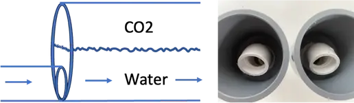
I see that your reactor is above your bypass, so the water exit tube from the reactor goes down, not up. This can work, but you need enough flow in your reactor so that bubbles will be taken with the flow, and go down. If the water flow is too slow, it may happen that the reactor and tubing above the bypass will fully fill with CO2 and the reactor function will be lost.


All what I am saying here only applies for overflow mode. When using the reactor below its max capacity, regulator or pH controller, there is no concern.
I am not completey sure what you mean by the water exit being down. With the bypass closed, the co2 and flow is directed into the reactor. The only down part is exiting the reactor a few inches and before going upward toward the tank. Do you mean the bypass should be on the same level as the reactor and not below it?

Also you were correct, I did not see any more significant change. My PH never made the full 1.0 drop either. Drop checker remained medium to dark green.
 
I am not completey sure what you mean by the water exit being down. With the bypass closed, the co2 and flow is directed into the reactor. The only down part is exiting the reactor a few inches and before going upward toward the tank. Do you mean the bypass should be on the same level as the reactor and not below it?

Also you were correct, I did not see any more significant change. My PH never made the full 1.0 drop either. Drop checker remained medium to dark green.
With the bypass closed as you say, all the waterflow will go through the reactor and when the reactor gets half full with CO2 (overflow mode) excess CO2 will be caried through the exit with the water flow. But obviously, a closed bypass is like having no bypass so what's the point. When you open the bypass, you will reduce the waterflow through the reactor. When the reactor is not yet at is maximum capacity (for example using CO2 regulator or controller) it will work like any other reactor, all CO2 will be dissolved and the enriched CO2/water flow will exit and to the tank. But what happens when the bypass is open, only a very small waterflow through the reactor, and the reactor is half filled with CO2 in overflow mode? Will the waterflow from the reactor, going a few inches down first, be strong enough to carry any excess CO2 bubbles, or will the CO2 bubbles push against the flow and all stay in the reactor.

I think you will be fine, but I posted about this so that other readers can benefit. I know at least one other user who has decided to build an improved version of the reactor, for overflow mode, where the waterflow after the reactor will go up.

Here is my reactor, water comes in from right, and flows to the left. I usually have my bypass valve fully open, so the main waterflow from my FX4 will go straight into the bypass and can leave the assembly on the left after passing only 2 (90 degrees / 1 inch diameter) corners. This should give just very little reduction in flow. Some water gets sucked into the reactor, I can observe that from the ripple on the water surface in the reactor. I am using the reactor in overflow mode, so when from time to time a small bubble exits the reactor with the slow flow it will only travel horizontally until the flow joins the high flow at the junction with the bypass flow. From there onwards, as we have high flow from the bypass I don't care too much if the tube goes up or down, it will be strong enough to pull bubbles with it.

A tube with a tube and a pipeDescription automatically generated with medium confidence

Whether we really need a bypass in an entirely different point. Without bypass the reactor will work, and I believe probably a majority use the reactor without bypass. The bypass is nice for fanatics like me, who want to optimise flow rate from pump, have absolutely no noise, and perfect overflow mode. But when the water gets injected low in the reactor, like the solutions below, it is pretty robust without overflow.

1717719073399.png
 
You are all going to find this funny but I used that picture as a model to create mine - -however I was unaware of the flow direction. Ooops!

Thankfully, all I need to do is just flip it around and reconnect the hoses, so it should work correctly. I will give it a try tomorrow. Haha!
 
Now that we're discussing the details, let me share some other trivia about optimising overflow mode.

In Horizontal CO2 Reactor - Yugang 鱼缸 Reactor I posted my reactor in situ, and you see that the water exit after the reactor points down. This gave me a little more space to use a 2 meter long Fluval hose curled up behind my tank. This was the situation at the time, I have now changed it and a short tube points straight up for the water to go to the tank.

1717723154713.png


The basic assumption of overflow mode is that excess bubbles from the reactor (ideally about 10-15%, as calculated earlier) will escape to the tank and disappear in ambient air without being dissolved in the water. This guarantees that when we have a stable reactor surface area the absorption into the water is independent of CO2 injection, ie independent of stability of our regulator. But this assumption does not hold if CO2 bubbles can accumulate somewhere in the tubing before they reach the tank, and these small CO2 pockets start acting as 'spurious reactors'. Curling up tubes, like I did, is therefore not the best idea for overflow mode as the top of the curls could build up gas pockets that start acting as small reactors and therefore make overflow mode less accurate.

This is my reactor today. I made it smaller, because I have come to the conclusion that stability is what really counts and I have no evidence that my plants need as much as 1.6 pH drop. Furthermore, I optimised for overflow mode and have a short tube from the reactor exit straight up to the tank. I see a few small bubbles escaping to the spraybar in the tank a few times per minute, and know that I am then fine. From time to time by the end of the day I observe how much gas stays behind in the reactor, and for those who followed the calculations that is another indicator if the overflow mode has been optimised.

1717723521329.png
 
Last edited:
Have you heard any plans for when the PVC or the stainless CO2 reactors will be made available at ARC?
Tommy has been a bit secretive about this and I’m shocked he posted about because he didn’t want us to post anything when he showed it to us . I know for a fact, Yugang has it in hand and is actively tearing it apart. There’s a few screws to fix on the “user friendly” side, but beyond that, I will say sooner than we think. It’s looking like a beautiful product though!
 
@Yugang has been so generous and helpful to me, held my hand through the calculations and parts questions, and opened to for to the world is CO2 reactors. I wanted to say thank you and that I appreciate your help.

Here's what we came up with. This is for a 60U (24" x 14") 20 gallon tank. 2" clear schedule 40 conduit 6" in length. At first, I mounted the reactor above the canister filter with both 90° elbows pointed down like so.IMG_20240606_194044515_HDR.jpg
This worked ok, but ( I'll add that I built another reactor for my smaller tank) the other reactor has a slightly different design due to space limitations and it worked better. Both of those 90° elbows faced up. So I moved the reactor down and turned both elbows upward like soIMG_20240609_043018315.jpg
The flow is more gentle and less bubbles. I control the CO2 flow with a regulator. I did not install a bypass or overflow. I'm using double tap disconnects for maintenance and flow adjustment purposes. I'm running an Oase 350 on this tank and need to throttle it down a bit anyways. This quiets everything down and stops the gurgling and sucking in air at the skimmer. I easily hit 1 ph drop in 40 minutes. I'm using a John Guest fitting for CO2 connection, which is threaded into reactor body using 1/8 x 27 NPT tap and 21/64 drill bit.

Such a huge improvement over the inline diffuser I was using. No more micro bubbles!
 
Okay @Yugang I want you to double check my math for my horizontal reactor build:

Tank Dimensions
Length: 914.4 mm/36"
Width: 457.2 mm/18"
Height: 425.45 mm/16.75"
Volume: 177865192.656 mm3/~40gal
Area: 418063.68 mm2
So with that its area / 17.7 = 23619.41695 mm2
So if I use a 3" pvc (75mm) * 914.4mm I get: 68580 mm2
If this is correct my reactor would be ~3x larger than I needed correct?

If that is the case and I reduce the size to 330.2mm length of the reactor I would get an area of 24765 mm2 for the surface area of the reactor itself and would this be sufficient to drop pH by ~1.5?

Also, question regarding overflow mode, when you are referring to it you mean having the bypass open on the reactor correct? I would like to do this as well but do not think I will have clear pvc. How critical is the clear to correctly adjust the flow?
 
Your calculations are correct @SkaleyAquatics .

If this is correct my reactor would be ~3x larger than I needed correct?
Correct. Frankly I see more downsides than advantages making such strong reactor. If you would use the reactor at full capacity this is likely to be an issue for life stock. So you may not want to do overflow mode with such large capacity, nor can you really rely on its inherent safety in case your regulator or controller would accidentally inject too much.

If that is the case and I reduce the size to 330.2mm length of the reactor I would get an area of 24765 mm2 for the surface area of the reactor itself and would this be sufficient to drop pH by ~1.5?
Correct. From all statistics I got until now it looks like this 17.7 ratio is very close to the 1.5 pH drop. This is under the assumption that the reference pH is fully outgassed, in outdoor air, and in equilibrium with 400 ppm ambient air. I emphasise this here, as I notice that there is often confusion around pH drop.

Also, question regarding overflow mode, when you are referring to it you mean having the bypass open on the reactor correct?
The injection rate in the reactor is virtually independent of the flow. So all the CO2 that gets injected will be mixed with any water that went through the bypass (open or closed) and will reach the tank. I use the bypass because I want a perfectly silent reactor, with only very little waves in the reactor, but this is in fact less critical for the reactor function and many use the reactor successfully without bypass.

Also, question regarding overflow mode, when you are referring to it you mean having the bypass open on the reactor correct? I would like to do this as well but do not think I will have clear pvc. How critical is the clear to correctly adjust the flow?
Not really critical, but I consider it a nice to have. When I see some gentle movement in my reactor it is a confirmation all is good, I also monitor how much gas is left after CO2 solenoid off, but I could run a reactor that is not transparent if I would need to.

@SkaleyAquatics send me a PM if you need further help in the process, I will be happy to support.
 

SkaleyAquatics that is an 1/4"OD x 1/8"NPT John Guest type fitting I got from Amazon.​

TAILONZ PNEUMATIC Elbow and Straight Combination 1/4 Inch Tube OD x 1/8 Inch NPT Thread Push to Connect Fittings PC-1/4-N1+PL-1/4-N1(Pack of 4)​

I used a 21/64" drill bit to drill a hole in conduit, then an 1/8 x 27 NPT tap to thread the hole. This fitting threads right into that. Use plenty of teflon tape.
 
The way my tank is set, I can't install it above the water line. My box isn't exactly like yours, it is longer and doesn't have the flaps on the large sides, only on the small sides. But that shouldn't be an issue with the recently added plastic clamps (not so sure about the translation here, maybe plastic bands?)

The rubber seal is more "delicate", with sort of an L shaped cross-section. I couldn't find it like yours in plastic, only in glass.

My first plan is to use a lot of silicon grease, since I have it here. If that doesn't work, I'll do the final test with silicon glue, but then I won't be able to iterate on the CO2 functionality, if the insides don't work, it's gone.
I gave up trying it sealed with silicon grease only and went for the silicon glue at once. I added as much glue as I could fit and waited 2 days for it to dry. But during my pressurized test, it leaked all around. I think maybe the glue doesn't adhere so well to the plastic.

And with that, I gave up on the compact reactor. This weekend I bought some PVC connections and started assembling a standard tubular horizontal reactor. No clear plastic, the insides will be a mystery.

I have this irrational aversion to having an excessively large gas pocket, thinking it could be wasteful, so after some basic math I came to the conclusion that a longer reactor with a smaller diameter will have a smaller gas pocket than a shorter reactor with a larger diameter.

Gas Volume = L * pi * D² / 8

L = A / D

Gas Volume = A * pi * D / 8

So, the larger the diameter, the larger the gas volume for the same surface area. That's for the ideal reactor geometry with the water limit at half the tubes height.

Considering the restriction of having the diameter at least twice the diameter of the tubing used, ideally even larger to account for the connections, in order to have the water level limited at half the reactor's height, I built my reactor with 50mm external diameter (~47mm internal). The sizing using the smaller area (smaller pH drop) gave me a 36cm long tube, so I rounded it to 40cm. Again I had some issues with the sealing during high pressure tests, but I already made a few adjustments that I believe will be enough. Just waiting for it to dry. I also think that my high pressure test may be a bit extreme, since the actual working pressure will be close to 1m of water column... And I'm testing with at least 4 times that.

Overall I'm hopeful that it will work this time and I should have it installed next weekend.

Just to recap, the tank's surface area is 1,3m x 0,5m.
 
I have this irrational aversion to having an excessively large gas pocket
You already make the point that the gas pocket may not matter too much, but let me still add and clarify a bit here for others readers of the thread.

When we turn CO2 off by the end of the day, we usually do that an hour or so before lights off. Indeed the reactor then still has the gas CO2 gas pocket inside, but this gas has nowhere to go but being absorbed in the water and will therefore not be lost. We just stop injecting CO2 a bit earlier before lights off, knowing that the gas pocket will make up for some time until gas absorption in the reactor fully stops.

The main reason why I don't care about my gas pocket is that its volume (assuming the reactor is half filled as in overflow mode) represents only a relative small part of the total injection during the day. I have my CO2 on for probably 10 hours, and when I take a typical 20-30 minutes for the gas pocket to disappear when the solenoid goes off this represents less than 5% of a full day.

So, the larger the diameter, the larger the gas volume for the same surface area. That's for the ideal reactor geometry with the water limit at half the tubes height.
This is true, as you say when the reactor is half filled as in overflow mode. But just for completeness, when the reactor is less than half filled, that is when we use it below its maximum capacity we can have the opposite situation as the below diagram illustrates. The small diameter tube is in overflow mode, but has a larger gas pocket than the large diameter reactor that operates far below its maximum capacity.

1718664053773.png

I am making some additional remarks about pipe diameters here, but the main point remains that there is no real need to worry about the gas pocket. The main reason I would not like a really short reactor with large diameter however is that that will probably give a bit more water turbulence at high flow rate and perhaps some noise and bubbles escaping.

since the actual working pressure will be close to 1m of water column...
This is correct, thank you for making the point. I've got several times questions how much CO2 pressure is needed for this reactor, and the answer is that you could blow in the bubbles with your mouth if you wanted too. The reactor works at very low pressure, both for water and CO2.
 
Great explanations! The illustration is also very... illustrative! One image is better than 1000 formulas.

Another concern that I had in this regard, and that I want to emphasize that it is of very little relevance, is that in overflow mode, the same formulas can be used for the water volume inside the reactor, indicating that the larger the diameter used, the more water. Then there could be a concern with the weight of the system. Also, a longer tube is cheap (especially if it is not transparent), while larger diameter connections get expensive fast.

All in all, it seemed like a good idea to have it made with a smaller diameter, especially since I'm using of the smaller surface area, so the reactor is still not too long.
 
1721257743185.png

This commercial reactor has asymmetric in and outflows, so that the reactor power can be adjusted. When the reactor power has been set for use in overflow mode, the reactor will help to stabilise the CO2 in the tank. For anyone using the reactor with a precision regulator or CO2 controller, rather than overflow mode, the reactor power can be limited so as to provide an additional safety when accidentally too much CO2 gets injected.

Note: I am offering my help to any manufacturer, have also supported for the above, and do this on a friendly non commercial basis as I believe this is some help we can give for progress in the hobby.
 

Top 10 Trending Threads

Back
Top