Welcome to ScapeCrunch

We are ScapeCrunch, the place where planted aquarium hobbyists come to build relationships and support each other. When you're tired of doom scrolling, you've found your home here.

Journal High-Tech 90P Build

Some minor updates.

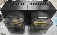
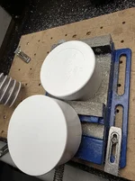
I got the AWC pump heads mounted to an enclosure. These will run on the same board as the dosing pumps.
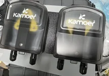
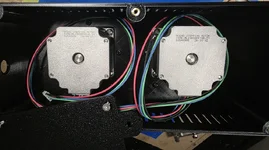
1783098652035.webp1783098665467.webp


1783098729867.webp

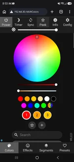
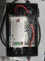
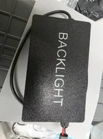
And I made a control box for an LED backlight using a prebuilt 4-channel ESP32 WLED module, inspired by @Mr. Silly Goose journal.
1783098784500.webp1783098798143.webp

I also added an extra connector to run a door switch, and an under cabinet light from the same module, because why not. I haven't figured out the backlight yet, but I'm thinking a piece of ACM panel that I have laying around, with some printed spacers, and white acrylic as a diffuser. The LEDs will be 5 strips of SK6812 RGBW.

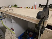
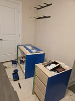
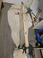
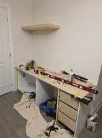
In the meantime, work continues on the stand build.
 
Last edited:
And I made a control box for an LED backlight using a prebuilt 4-channel ESP32 WLED module, inspired by @Mr. Silly Goose journal.

View attachment 18182View attachment 18183

I also added an extra connector to run a door switch, and an under cabinet light from the same module, because why not. I haven't figured out the backlight yet, but I'm thinking a piece of ACM panel that I have laying around, with some printed spacers, and white acrylic as a diffuser. The LEDs will be 5 strips of SK6812 RGBW.

In the meantime, work continues on the stand build.
Would love more details about the backlight. I'm not sure where I'd even start, but would welcome a DIY solution 😁
 
Life has been busy lately, but decided to stay up and work on the backlight a bit.

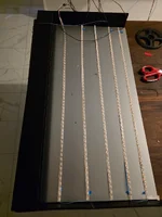
I 3d printed the case, still need to print the top. Bottom and top in 3 parts and sides in 2 parts epoxied together. The back is leftover Acm, and I purchased some 3mm white acrylic for the front diffuser.

Wiring it all up took a couple hours, and haven't mounted the leds to the Acm just yet, as I haven't decided between a staggered offset more biased towards the top as the bottom of the tank will be mostly covered by substrate/hardscape/plants. Same reason why I made the bottom a few inches high, it gave a more hefty stable base and reduced the need for an extra row of LEDs.

Not sure if I can attach an HD video, but I made a quick gif, the strips allow for any sort animated effects, but the stagger is noticeable here. But on the solid gradients, I prefer the stagger more, and I doubt I'm going to animate the background except for party tricks.

Keen eye will notice the shadow at the bottom and light bleed at the top, the diffuser is just sitting on the box, once I get the top of the box printed, I'll be able to mount it and that will disappear.

Now that I know it works, I'll clean up the wiring and mount the strips.

20260711_001857(1).webp

20260711_002745.webp20260711_002716.webp
 
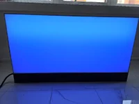
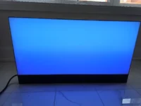
Finished off the backlight, had to do a bit of final trimming and accidentally took a bit too much off the front diffuser, but you can't tell too much. 🫣

Wled works really well with it, and anyone familiar with it knows the endless effects and colours it enables.

The 3d printed frame works well enough, but if I were to start again, I might have gone with mdf or possible aluminum angle instead as there are slight seams that leak a bit of light when viewed at perfect angles, I will have to fill these if it bothers me enough.

20260713_203453.webp

Wiring is all cleaned up, and did heavy testing before Sealing the panel on with silicone. If something inside breaks, I'll have to break open the 3d printed panels to get to the guts.

20260713_182852.webp


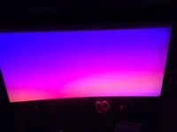
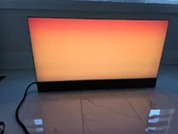

Gradients are easy to do and look better in person than on the pictures, and are fully adjustable from rows 1-5, and even within the rows. I'll need to experiment with radial gradients for sunrise/sunset, I think it could look really cool.

20260713_202436.webp20260713_202805.webp
20260713_202831.webp
A couple animations, gifs as the videos are too large to upload.
20260713_202600(1).webp
20260713_203400(1).webp

Lightning mode is fun too.

View attachment 20260713_203049~2.mp4
With wled doing the heavy lifting it will be easy to integrate into home assistant and sync with the overhead lights.

Screenshot_20260713_205012_Chrome.webp

Happy to help anyone that wants to build one with 3d files or wiring, it ended up being a lot simpler than I thought, only downside is it's chunky (~4" thick) compared to commercial offerings given it uses physical depth to diffuse the light vs what I suspect are edgelit panels in the UNS units. But with the animation ability, and per Led customizability, timers, and syncing with other lights it's better in other ways. The wled module was only about $20, and the leds about $20 for 5m, $30 for the acrylic diffuser panel and another $25 for the PSU.

The Acm, wiring bits and all I already had on hand. So not counting that and the 3d printed bits, I'm at about $100CAD invested into it.
 
Last edited:
The Acm, wiring bits and all I already had on hand. So not counting that and the 3d printed bits, I'm at about $100CAD invested into it.
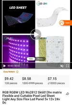
This is what I was curious about. I'd previously looked at some light panels on Alibaba that you could get in various sizes and even custom sizes in quantities as low as 1 (sample) for really cheap.
 
Finished off the backlight, had to do a bit of final trimming and accidentally took a bit too much off the front diffuser, but you can't tell too much. 🫣

Wled works really well with it, and anyone familiar with it knows the endless effects and colours it enables.

The 3d printed frame works well enough, but if I were to start again, I might have gone with mdf or possible aluminum angle instead as there are slight seams that leak a bit of light when viewed at perfect angles, I will have to fill these if it bothers me enough.

View attachment 18495

Wiring is all cleaned up, and did heavy testing before Sealing the panel on with silicone. If something inside breaks, I'll have to break open the 3d printed panels to get to the guts.

View attachment 18491

Gradients are easy to do and look better in person than on the pictures, and are fully adjustable from rows 1-5, and even within the rows. I'll need to experiment with radial gradients for sunrise/sunset, I think it could look really cool.

View attachment 18492View attachment 18493
View attachment 18494
A couple animations, gifs as the videos are too large to upload.
View attachment 18496
View attachment 18497

Lightning mode is fun too.
View attachment 18498

With wled doing the heavy lifting it will be easy to integrate into home assistant and sync with the overhead lights.

View attachment 18499

Happy to help anyone that wants to build one with 3d files or wiring, it ended up being a lot simpler than I thought, only downside is it's chunky (~4" thick) compared to commercial offerings given it uses physical depth to diffuse the light vs what I suspect are edgelit panels in the UNS units. But with the animation ability, and per Led customizability, timers, and syncing with other lights it's better in other ways. The wled module was only about $20, and the leds about $20 for 5m, $30 for the acrylic diffuser panel and another $25 for the PSU.

The Acm, wiring bits and all I already had on hand. So not counting that and the 3d printed bits, I'm at about $100CAD invested into it.
Wow, looks great! That color gradient is something I would love to have! Can't wait to see it once the tank is set up!
 
This is what I was curious about. I'd previously looked at some light panels on Alibaba that you could get in various sizes and even custom sizes in quantities as low as 1 (sample) for really cheap.
I think I know the ones you're talking about, just single colour selectable panels right? Good idea, and it would probably work. They also have 2d matrix led sheets that could work even better than the strips I used at the cost of The larger PSU. It would also greatly simplify the wiring. They would provide even better animation ability.

46297.webp

Wow, looks great! That color gradient is something I would love to have! Can't wait to see it once the tank is set up!
Thanks! Happy to help you design one if you ever wanted to put one together! I really need to get back on the stand instead of getting distracted by these side projects 😂
 
Been a few weeks, so a small update on progress.

1786038795712.webp
Coated the interior of the cabinet with rustoleum white appliance epoxy since that seems like the thing to do. It seems quite durable, though it stank while curing.

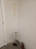
Also finished running the AWC, ATO, CO2 lines from the basement - and added a dedicated GFCI circuit to the side wall. In addition, as per my plan, ran a pull line (yellow wire) for my LED light fixture to where the first floating shelf will end up.

1786038973602.webp

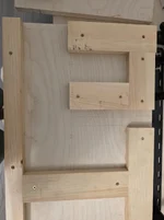
Then made up a couple of floating shelves out of 3/4 ply - 3/4 scraps - 3/4 ply sandwich with a veneer layer on the visible sides.


1786039030539.webp1786039038174.webp1786039138956.webp

They are hollow-ish inside so I can pull the wire for the lights through later when mounted.

1786039097045.webp
I then built the drawer cabinet for the right side of the built-in, and test fit the floating shelf.

1786039225049.webp
The boss chose the colours for the wall and cabinets - not me questioning the blue after the first coat, she says it will get darker.


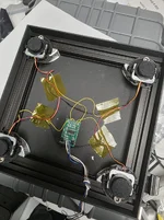
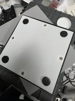
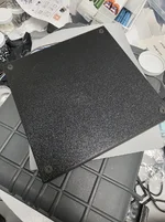
In the meantime, I put together my load cell sensor for the CO2 tank - components are just a $7 kit from Aliexpress, some spare extrusion that I chopped up, and some 3d printed parts.

1786039395925.webp1786039406227.webp1786039420629.webp

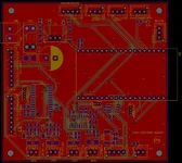
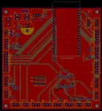
I've also got the circuit boards designed in the last couple of weeks, and sent them all out for manufacture.

1786039701581.webp
Powerbar
1786039735929.webp
Basement control

1786039790083.webp
Sump/main controller

1786039819613.webp
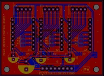
And of course the 3-channel dosing pump boards. Ordered a few extra of these in case anyone wants them later.

I've also started my Yugang reactor build - I liked the idea of being able to rotate the reactor to reduce the power, but wasn't able to find any offset fittings near me. I ended up ordering 4" caps to fit my clear PVC tube as the 4" ones at Home Depot were too small. I planned to use bulkhead fittings drilled in offset, but once they arrived - they surface wasn't flat, and they had a ring on the inside. So had to trim that all off.

1786040206424.webp1786040215486.webp
This was more of a pain than it looks to be, as I didn't have router bits that are super long for the inside milling.

On a side note, does anyone know how to adjust the Yugang formula when dealing with a sump? I plan to put some sort of cover on it, but also figure there will be some loss from the churning water as well. My plan right now unless anyone can advise better is to overbuild the Yugang slightly and use the rotation to limit it once I have a better idea of co2 loss with the sump.

All in all, things are moving forwards but slowly as I've had to steal an hour here or there to work on it. I need to finish work on the cabinet and counter, as well as build doors/drawer faces and mount it all together. Once the PCBs come in, there will be a lot of assembly and testing that will need to happen as well. Flooding the tank still seems so far away!
 
On a side note, does anyone know how to adjust the Yugang formula when dealing with a sump? I plan to put some sort of cover on it, but also figure there will be some loss from the churning water as well. My plan right now unless anyone can advise better is to overbuild the Yugang slightly and use the rotation to limit it once I have a better idea of co2 loss with the sump.
There will be quite a bit of loss of CO2 with a sump, especially one without a lid. You should add the rough area of exposed water-to-air to the formula with the rest of your tank.

For example, if your tank was 120cm long by 60cm deep (front to back), that's 7200cm2 of area that CO2 can escape. But, if your sump was 90x45cm of open top too, that's 4050cm2 to add to your calculations. So, add both and divide by the "power" ratio. Yugang recommends 17, but I recommend 15 for more power.

11,250cm2 / 15 = 750cm2 reactor max size needed to reach at least a ~1.1pH drop (divide by 13 for even more power, or 17 for standard Yugang calculations).

Your pipe size is 10.16cm in diameter (4"), so you would need this: 750cm/10.16cm = ~74cm long four-inch pipe to fulfill the length needed to reach a reactor at 1/15th power.

You could make this tube longer if you will have rotatable, offset water exit to adjust your reactor's power, which is what I recommend. You can always make it more powerful, and adjust it down later -- but once created, you can't ever increase the power beyond the original maximum.

All in all, things are moving forwards but slowly as I've had to steal an hour here or there to work on it. I need to finish work on the cabinet and counter, as well as build doors/drawer faces and mount it all together. Once the PCBs come in, there will be a lot of assembly and testing that will need to happen as well. Flooding the tank still seems so far away!
It's looking great! You'll love all the effort your putting in now later. People so often leave this hobby because algae and all the annoying things pile up, but if you remove as many obstacles to enjoyment as possible early on, these tanks become really easy to work with.
 
There will be quite a bit of loss of CO2 with a sump, especially one without a lid. You should add the rough area of exposed water-to-air to the formula with the rest of your tank.

For example, if your tank was 120cm long by 60cm deep (front to back), that's 7200cm2 of area that CO2 can escape. But, if your sump was 90x45cm of open top too, that's 4050cm2 to add to your calculations. So, add both and divide by the "power" ratio. Yugang recommends 17, but I recommend 15 for more power.

11,250cm2 / 15 = 750cm2 reactor max size needed to reach at least a ~1.1pH drop (divide by 13 for even more power, or 17 for standard Yugang calculations).

Your pipe size is 10.16cm in diameter (4"), so you would need this: 750cm/10.16cm = ~74cm long four-inch pipe to fulfill the length needed to reach a reactor at 1/15th power.

You could make this tube longer if you will have rotatable, offset water exit to adjust your reactor's power, which is what I recommend. You can always make it more powerful, and adjust it down later -- but once created, you can't ever increase the power beyond the original maximum.


It's looking great! You'll love all the effort your putting in now later. People so often leave this hobby because algae and all the annoying things pile up, but if you remove as many obstacles to enjoyment as possible early on, these tanks become really easy to work with.
Thanks, this helps a ton! I do plan to have a lid on the sump, but I know it will not be airtight and the water agitation in the first chamber will churn up co2. But good call on oversizing and just reducing power as needed.

Display: 88 × 43 = 3,784 cm²
Sump raw: 75 × 30 = 2,250 cm²
Total: 6034 cm²

ID of my pipe is 10.2cm

/13 = 464 cm² / 10.2 = 45.5 cm
/15 = 402 cm² / 10.2 = 39.4 cm
/17.7 = 341 cm² / 10.2 = 33.4 cm

I take it that setting in the min position would reduce volume well below 341 cm², so going bigger should be fine. Thanks @Naturescapes_Rocco for helping me through that, appreciate it!

Also agree on removing obstacles, and I truly enjoy doing the diy work, so it's not all bad.
 
make this tube longer if you will have rotatable, offset water exit to adjust your reactor's power, which is what I recommend. You can always make it more powerful, and adjust it down later -- but once created, you can't ever increase the power beyond the original maximum.

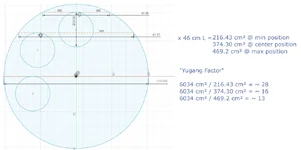
I was curious HOW adjustable rotation would be based on my factors of 10.2cm diameter, 3/4" fittings, and an offset of 3.3cm from the cap to bulkhead center, so I ran the numbers:

1786114044282.webp

6034 cm² being my tank + sump surface area as per last post. In effect, I can adjust anywhere between a "Yugang Factor" of 13 to as low as 28, pretty awesome.
 
Really glad to see you measure from the top of the exit. I'm seeing a lot of users build a regulator (with 1/17th power) with a centered output, but not realizing that they needed a bit more length to account for the actual exit height in the system. Then their reactor is underpowered and they don't see the results they expected!

I know it makes the builds more complicated, but a rotatable, adjustable oversized reactor is by far the most important aspect of these reactors IMO!
 
Last edited:
Been a couple weeks with a little bit of progress.

The circuit boards came in and look great, I've populated them all which took some time, and I think I finally get why my optometrist suggested bifocals, advise which I ignored.
1787586787088.webp 1787586798476.webp

Still testing to be done - haven't written or uploaded any code yet, as I want to design and fit the enclosures/connectors first.

1787586867770.webp1787586900945.webp
The cabinet area is looking a lot better after like 5-6 coats of paint. Also begun on making the drawer and door face frames.


1787587294992.webp
Printed some frames for the outlet pass through, and water/co2 line passthroughs from the wall, as well as a vent and fan to combat any humidity buildup given the interior of the cabinet is mostly sealed.
1787587361153.webp1787587372707.webp1787587789798.webp


Lastly, I finally got around to water testing the overflow box I built way back in this thread, and its a success!

1787587542418.webp

Next steps - controller enclosures, basement cabinet for the AWC/Mixing Tank/CO2 tank.

Weather pending, I want to drill the tank this week... never done one before, so still super nervous about it, especially since I'm doing it on the short side, and being a rimless tank.

1787587628312.webp

If anyone has some advice, please share. I'm really hesitant to stand it up on its short side to drill, but I know that is the best way for water and dust evacuation. I've made a couple of 3D printed templates to get the holes where I need them - and now its a matter of just doing it.
 
Due for another build update...

After getting the tank drilled, I was able to start on the sump plumbing and laying out the various bits in and on the cabinet.

I put the backlight in place behind the tank, and turned it on for a quick test only to realize most of the led strips adhesive had come undone while sitting. If you remember from when I built it, I siliconed it all together which meant I had to break it open, here's what I found. Luckily the wires were all intact, so I siliconed all the strips in place and resealed the box.

20260830_223558.webp

I also plugged all the level adjustment holes in the stand as I'll place a leak sensor in later. I used size 000 rubber stoppers and trimmed them to fit flush. They can still be removed with some effort prying with a small flat screwdriver.

20260911_224609.webp

Next I decided to tackle the overflow box, and mounted that plus drilled the deck for the plumbing. Also added some black vinyl to this wall to hide said plumbing.

20260830_222817.webp
20260911_233053.webp

I then built my yugang reactor and began plumbing. Mounted the yugang with some 3D printed clamps, and also designed some clamps for the overflow piping seen on the left of this pic. I haven't tightened them yet as I expect the tank and plumbing to sink a tiny bit once filled at which point I can close the clamps fully so the pipes aren't pulling down on the overflow box and tank glass.

20260910_181909.webp

I offset the bulkheads for the reactor so I can simply loosen the mounting clamps, rotate and retighten to lock it in again.

20260911_233504.webp
I then plumbed in the co2 line through a flow meter (idea stolen from others here of course), and again 3D printed a custom bracket for it.

20260911_224349.webp 20260911_224352.webp

Also had to 3D print new fittings for the uv clarifier as the stock ones were way too long given my space constraints. Time will tell if they hold up or leak.

20260911_233231.webp 20260908_202323.webp


Here's a look at how the plumbing stands currently.

20260911_232826.webp
I have to finish all 3 overflow drains into the sump, and the return pipe from the pump to the uv clarifier.

20260911_225747.webp

As for the sump, it's obviously way overkill for a 90p tank, but necessary for the awc and top off automations I wanted, so I decided to make the middle chamber a refugium for neos so I can repopulate the display readily since I expect some predation. The first chamber will be turbulent then pass through a large 38mm wide filter, which you guessed it, 3D printed in 3D printed channel siliconed to the glass 😁.

The first one I made was one piece, but realized I can't pull it out as it hits the yugang above, so replaced it with a 2 piece design with a half lap joint so they slot into each other.

20260911_232942.webp

Within the refugium section, I printed more of the same filter material in cubes which I'll plant with java moss most likely.

20260911_232908.webp

Then between this and the last chamber is some 2" 35ppi foam and a fine ss mesh to keep shrimplets contained, with some eggcrate backer that I tied the mesh to. The mesh and eggcrate combo is siliconed in place, and the foam slides in to a similar channel as the chamber 1 filter.

20260911_232919.webp

Also printed lids for chambers 1 and 2.
20260911_232926.webp

The chamber 2 lid is a printed frame with an acrylic window, and designed this lightbox to sit on top which I'll fill with some leftover led strip. It will also get powered by the same esp32 and PSU that runs the backlight.

20260911_233439.webp
I also printed some locline style fittings for the return line in the tank, but I absolutely hate the look. I want to replace it with something else, just not sure what yet as this is way too bulky and imposing.

20260911_233541.webp 20260910_224019.webp

One thing I didn't really plan for is how much space I would need in the cabinet for the sump, yugang, and all related plumbing. Once it was all in there I realized I'm going to have a hell of a time fitting in all the tech. The plumbing running left to right and the yugang having to be mounted towards the rear blocked all the good wall and ceiling real estate in the cabinet.

I did get the powerbar all wired up in an enclosure, and managed to squeeze it in between a couple of the cross supports under the deck, and between all the plumbing. I used a cleat style mount so I can still remove it if I have to get to a fuse.

Each line has its own fuse, and the heater control circuit in particular has a solid state relay and a regular relay in line so that I can keep a stable temperature with pid style control and no click on/click off noise. The regular relay is in place as solid state relays tend to fail closed if they die so that acts as protection.

Additionally, since the heater I'm using does not have its own thermostat, the circuit has a pulse mechanism such that the main controller must send a pulse every x seconds to keep the heater alive. So if the controller ever froze or if the link to the controller malfunctioned, the pulse wouldn't fire and the heater turns off. I put the same pulse mechanism on the pump power as well. Both of these kill circuits have direct lines back to the controller, while the other relays being for less critical equipment get fired on/off via i2c. Happy to explain further if anyone is curious.

20260911_214652.webp

20260911_214727.webp

20260911_221914.webp

20260911_224154.webp

That leaves me to the current state, where I have the backlight psu/controller, the main led psu/controller, the fertilizer dosing pumps and of course the main controller all still needing a home in the cabinet with not a lot of ideal spots to install. One or two of them will have to go somewhere a bit risky in a leak, or somewhere less accessible without removing the sump which isn't ideal, and I want to save the inner side of the cabinet doors from having any wires, so still figuring this one out.

20260911_232817.webp

Other than that, I did get the led wired through the shelf, wall and into the cabinet, heres how it looks so far.


20260911_233124.webp

The wire hangers work nice, I still need to cut the excess and put some safety stops on them.
20260911_233649.webp

Lastly, I built the basement cabinet for the mixing tank, and co2 canister and primed it. Same with the main cabinet doors and drawer fronts.
20260911_233335.webp 20260911_233321.webp 20260911_233357.webp

That's it for now!
 
Last edited:
Back
Top