with my fx6, would you think id be better off building a bypass in or my other option I have a spare Fluval 206 laying around that I could run though it separately (could buy a small filter/pump if needed). Heres my tank setup that im trying to do all this on.....It sounds like you are either overflowing CO2 too much or otherwise losing CO2 straight through the reactor and out as bubbles rather than allowing it to diffuse into the water. Too strong flow through the reactor is a common problem. THese work so much better with nice slow flow - ideally minimal visible surface disturbance. I'm not sure how the Aqua ROcks Colorado ones plumb in, but putting an FX6 outflow through one of these sounds much too strong a flow without a bypass circuit built in to reduce actual flow through the reactor. I suspect you are blowing quite a lot of CO2 bubbles straight through the reactor without diffusing into the water.
Solutions would seem to be either building a bypass circuit to adjust the water flow through the reactor, or using a much slower pump for a separate reactor circuit
Here's my homemade reactor and bypass cicuit ......
Navigation
Install the app
How to install the app on iOS
Follow along with the video below to see how to install our site as a web app on your home screen.
Note: This feature may not be available in some browsers.
More options
Style variation
Welcome to ScapeCrunch
We are ScapeCrunch, the place where planted aquarium hobbyists come to build relationships and support each other. When you're tired of doom scrolling, you've found your home here.
You are using an out of date browser. It may not display this or other websites correctly.
You should upgrade or use an alternative browser.
You should upgrade or use an alternative browser.
Another Yugang post
- Thread starter Nlg1002
- Start date
- Tagged users None

I'd recommend a bypass! And see my post here about where the bypass should be:
You can also run two return lines, where one has a valve for slow reactor flow and the other is fully open for max flow. Two return lines in a tank helps with good circular flow, too:

Not hating at all (you know I'm a big fan!!) but from my understanding of flow, I think this design would work even better if the reactor was in the middle, and the bypass on the outside.
The current design:

Water takes the "path of least resistance", which is mostly through the reactor. Probably 90% of the water flow goes through the reactor no matter what, and ~10% can be adjusted with the valve, in the current orientation, due to friction around the corner, etc. Not all, but most, flow goes through the reactor, so maybe not much can be adjusted with the valve.
If you were...
The current design:
Water takes the "path of least resistance", which is mostly through the reactor. Probably 90% of the water flow goes through the reactor no matter what, and ~10% can be adjusted with the valve, in the current orientation, due to friction around the corner, etc. Not all, but most, flow goes through the reactor, so maybe not much can be adjusted with the valve.
If you were...


You can also run two return lines, where one has a valve for slow reactor flow and the other is fully open for max flow. Two return lines in a tank helps with good circular flow, too:
JayP
Valuable Member
I'm still considering a bypass for my ARC small reactor but the trick on those is finding the best fittings to work with ARC's since they're not standard U.S. sizes other than the barbs themslves.I'd recommend a bypass! And see my post here about where the bypass should be:
Not hating at all (you know I'm a big fan!!) but from my understanding of flow, I think this design would work even better if the reactor was in the middle, and the bypass on the outside.
The current design:
Water takes the "path of least resistance", which is mostly through the reactor. Probably 90% of the water flow goes through the reactor no matter what, and ~10% can be adjusted with the valve, in the current orientation, due to friction around the corner, etc. Not all, but most, flow goes through the reactor, so maybe not much can be adjusted with the valve.
If you were...
You can also run two return lines, where one has a valve for slow reactor flow and the other is fully open for max flow. Two return lines in a tank helps with good circular flow, too:
The couplings are 25mm (euro sizing) which you can get all 25mm PVC parts on amazon, OR you can get some 3/4" PVC Union couplings, which will actually fit the existing reactor sizes! I already did this previously and it worked great.I'm still considering a bypass for my ARC small reactor but the trick on those is finding the best fittings to work with ARC's since they're not standard U.S. sizes other than the barbs themslves.
I used these, kept the original "screw ring" from the 25mm size. The flat half of the 3/4" union can sit just fine over the gasketed-side of the existing 25mm union. Tighten them down with the original 25mm screw ring, and you just adapted to 3/4" PVC for your builds.

with my fx6, would you think id be better off building a bypass in or my other option I have a spare Fluval 206 laying around that I could run though it separately (could buy a small filter/pump if needed). Heres my tank setup that im trying to do all this on.....
In truth, either strategy would work. There is actually a benefit of not having the reactor set up on your main canister filter. It the reactor is set up on your FX6 then each time the filter is turned off for tank/filter maintenance/cleaning, CO2 addition to the tank is lost. If you are anything like me then CO2 is timed to be injecting up to around 7pm so if I want to avoid shutting the CO2 off to the tank then I have to do all maintenance that involves shutting CO2 off after 7pm, which is a bit of a pain. I also generally turn my filters off during the weekly tank cleaning/water chnaging session, which lasts around 1-5 to 2 hours. Ideally I wouldn't want to have CO2 shut off for that length of time. So, having the reactor running via a separate smaller filter or pumped circuit that can continue dribbling into the tank during the whole tank cleaning session is still fine.
If building the reactor into a bypass circuit on the FX6 output then I'd thoroughly recommend having the control valve in the reactor side of the circuit NOT the bypass side. It will give you far more control to achieve low flows through the reactor by having the valve in the reactor side of the circuit. If you have the control valve in the bypass side of the circuit then the minimum flow achievable in the reactor is generally only around 50% of the filter output, which may well be more than you want/need trhough the reactor.
Maybe I misread and we're on the same page, but my initial thought to your phrasing was that I didn't agree. Let me know what you think:If building the reactor into a bypass circuit on the FX6 output then I'd thoroughly recommend having the control valve in the reactor side of the circuit NOT the bypass side. It will give you far more control to achieve low flows through the reactor by having the valve in the reactor side of the circuit.
From my understanding, Option 1 is the worst option of them all, with 2a/2b/2c all better in terms of actual flow control through the regulator:
Option 1: tee on the bypass

Option 2a:

Option 2b:

Option 2c:

Maybe I misread and we're on the same page, but my initial thought to your phrasing was that I didn't agree. Let me know what you think:
From my understanding, Option 1 is the worst option of them all, with 2a/2b/2c all better in terms of actual flow control through the regulator:
Option 1: tee on the bypass
View attachment 16128
Option 2a:
View attachment 16129
Option 2b:
View attachment 16130
Option 2c:
View attachment 16131
In all of your pics the valve is situated in the bypass side of the curcuit. What I am suggesting is placing the valve in the part of the circuit next to the reactor, so that one could theoretically shut off flow completely through the reactor. This will allow you adjustability of flow through the reactor to much lower levels than having the valve in the bypass section of the reactor (where minimum flow through the reactor is roughly 50% of pump output).
Having the valve in the reactor section of the bypass circuit, as I suggest, the maximum reactor flow is roughly 50% of the pump output but this is ample and seems far more appropriate for higher flow pumps.
Here's a pic of mine (although it is very Heath Robinson in construction, you will see that I can turn flow through the reactor down to extremely low levels if I want to. The angle of flow through the bypass is a little tortuous I'll agee, but it still amply copes with the flow expected from it.

Here's my homemade one. You can see that the CO2 bubble fills nearly half the reactor. It can't get any bigger because it will burp and overflow bubbles out of the reactor outlet. At night the CO2 switches off, and the bubble shrinks right down, due to residual nitrogen in the bubble (which is not absorbed quickly by the water). When the CO2 switches back on in the morning the bubble grows quickly, until it's maximum size is limited by the position of the outlet (which then overflows CO2 bubbles every minute or so). THis is how running in overflow mode works and is the safest mode...
I replied to the wrong thread, but we're actually on the same page. The point isn't which "side" the valve is on in relation to the reactor, it's that the valve needs to be on the side where the "main" flow is going for proper control. In my photos (which are correct) the valve controls the main flow, and diverts it to the secondary flow when closed. It's the same for yours, which is also correct! Even though the reactor is on the other "side", it's the same principle.
Lol. Its so difficult having this discussion via message but I think we are getting closer to understanding each other. I think I actually see it different to you. Whether the valve is pre or post the reactor I see the benefits of having the valve in the arm of the circuit which controls flow through the reactor, NOT through the bypass arm of the circuit.
I know what you're thinking, but you're only thinking about YOUR setup. It's one of those "square is a rectangle, but not all rectangles are squares" scenario. I'll try to explain my best!
This depends on how the system is setup and how the bypass is "tee'd" off. There are times where the benefits of having the valve on the same arm as the reactor ISN'T of benefit.
Example 1a: Flow is correct, despite valve on opposite arm from reactor

Example 1b: Flow primarily skips arm with valve, majority of flow isn't controlled (despite valve being on reactor side).

Example 2a:Flow is correct, with valve on same arm from reactor:

Example 2b: Flow primarily skips arm with valve, majority of flow isn't controlled.

This property applies to setups where it has two return lily pipes, too:
Example 3a:Flow through system is properly controlled with valve on reactor side

Example 3b: Flow primarily skips arm with valve, majority of flow isn't controlled.

Switch where the reactor is relative to the "Tee":
Example 4c: Flow is correct, despite valve on opposite arm from reactor.

Example 4d: Flow primarily skips arm with valve, majority of flow isn't controlled.

Example 5a: Niche case, where there is no "main" path of flow because the Tee fitting splits the flow equally. Technically you have same amount of control whether the valve is on the reactor arm or not:


You'd have the same control/flow because of the evenly split tee, but the overall AMOUNT of control/flow you have is far less than if you just...
...6a:

6b:

Or, if you swap the arms where the reactor is:
7a:

7b:

Water doesn't like to turn corners, ever, unless it's either forced to by gravity or because it has nowhere else to go. Water will ALWAYS choose the path of least resistance, so we want our valve to be placed in the path of least resistance, not the path of most resistance. This is an important basic for fluid dynamics.
Hopefully these examples help show the most important truth: What is most important to control the flow through your reactor is to always have the valve on the "main" arm, the one where the water has the path of least resistance. Sometimes that's on the reactor side, sometimes that's on the bypass side, but it should always go on the reactor side for full control.
I hope this makes sense! Your reactor is set up properly, because it technically looks like this:

Whether the valve is pre or post the reactor I see the benefits of having the valve in the arm of the circuit which controls flow through the reactor, NOT through the bypass arm of the circuit.
This depends on how the system is setup and how the bypass is "tee'd" off. There are times where the benefits of having the valve on the same arm as the reactor ISN'T of benefit.
Example 1a:
Flow is correct, despite valve on opposite arm from reactorExample 1b:
Flow primarily skips arm with valve, majority of flow isn't controlled (despite valve being on reactor side).Example 2a:
Flow is correct, with valve on same arm from reactor:Example 2b:
Flow primarily skips arm with valve, majority of flow isn't controlled.This property applies to setups where it has two return lily pipes, too:
Example 3a:
Flow through system is properly controlled with valve on reactor sideExample 3b:
Flow primarily skips arm with valve, majority of flow isn't controlled.Switch where the reactor is relative to the "Tee":
Example 4c:
Flow is correct, despite valve on opposite arm from reactor.Example 4d:
Flow primarily skips arm with valve, majority of flow isn't controlled.Example 5a:
Niche case, where there is no "main" path of flow because the Tee fitting splits the flow equally. Technically you have same amount of control whether the valve is on the reactor arm or not:You'd have the same control/flow because of the evenly split tee, but the overall AMOUNT of control/flow you have is far less than if you just...
...6a:
6b:
Or, if you swap the arms where the reactor is:
7a:
7b:
The summary here is:
Water doesn't like to turn corners, ever, unless it's either forced to by gravity or because it has nowhere else to go. Water will ALWAYS choose the path of least resistance, so we want our valve to be placed in the path of least resistance, not the path of most resistance. This is an important basic for fluid dynamics.
In SOME cases that is a true statement, but there are other cases where that is false. It's not a blanket true statement that what matters is that the valve is "always on the arm of the reactor". Sometimes it is supposed to be on the opposite side. It depends on how your tee is oriented, and which arm contains the "main" flow, aka the path of least resistance, for the water.I see the benefits of having the valve in the arm of the circuit which controls flow through the reactor
Hopefully these examples help show the most important truth: What is most important to control the flow through your reactor is to always have the valve on the "main" arm, the one where the water has the path of least resistance. Sometimes that's on the reactor side, sometimes that's on the bypass side, but it should always go on the reactor side for full control.
I hope this makes sense! Your reactor is set up properly, because it technically looks like this:
Attachments

Last edited:
Kwyet
After every new tank—“This is my last one!”
I thought I was following this, until you got to 6a and 6b. Isn’t the valve on the main arm/path of least resistance on 6b? I don’t plan on making one, but I would like to understand.
Oops, had the photos switched. Now it's fixed!
always have the valve on the "main" arm, the one where the water has the path of least resistance. Sometimes that's on the reactor side, sometimes that's on the bypass side, but it should always go on the reactor side for full control.
This seems like an excellent golden rule.
I do understand now. You were taking into account the fluid dynamics across the T-junction, whereas I had not been. I was assuming that every system's flow layout would be like mine (your diagram 2a) which is of course not true. Thanks for correcting me. Thats not a mistake I really should have been making (I used to actually teach physics a long time ago !!). I seem to have arrived at a good configuration by intuition when constructing mine ! It certainly was not by intentional design.
However, in the equal flow circuit (5a), surely having the valve on the reactor arm side will allow you roughly 0-50 % of the pump flow ? Whereas if you have the valve on the plain arm of the circuit you will only be able to adjust between the range of roughly 50-100% of the pump output through the reactor. Thus completely different potential flow ranges through the reactor. I do see how 6a is better than both though, allowing you potentially a range of roughly 20-100% of pump output through the reactor.
It seems to me that the very best layout is 2a/3a/7a (which are all pretty much the same circuit for fluid dynamics), which will allow you roughly a 0-80% pump output range of adjustment through the reactor.
All my figures here are assuming roughly an 80 : 20 split of water flow across a T-junction.
Anyway, thanks for clarifying it all.
I have just started setting up a cerges reactor (the vertical setup fits my cabinet layout better) and am planning to install it in the following configuration. It hasn’t been thread sealed and there is a bushing yet to arrive for the CO2 inlet.I know what you're thinking, but you're only thinking about YOUR setup. It's one of those "square is a rectangle, but not all rectangles are squares" scenario. I'll try to explain my best!
This depends on how the system is setup and how the bypass is "tee'd" off. There are times where the benefits of having the valve on the same arm as the reactor ISN'T of benefit.
Example 1a:
View attachment 16177
Example 1b:
View attachment 16178
Example 2a:
View attachment 16179
Example 2b:
View attachment 16181
This property applies to setups where it has two return lily pipes, too:
Example 3a:
View attachment 16182
Example 3b:
View attachment 16183
Switch where the reactor is relative to the "Tee":
Example 4c:
View attachment 16184
Example 4d:
View attachment 16185
Example 5a:
View attachment 16186
View attachment 16187
You'd have the same control/flow because of the evenly split tee, but the overall AMOUNT of control/flow you have is far less than if you just...
...6a:
View attachment 16189
6b:
View attachment 16188
Or, if you swap the arms where the reactor is:
7a:
View attachment 16191
7b:
View attachment 16190
The summary here is:
Water doesn't like to turn corners, ever, unless it's either forced to by gravity or because it has nowhere else to go. Water will ALWAYS choose the path of least resistance, so we want our valve to be placed in the path of least resistance, not the path of most resistance. This is an important basic for fluid dynamics.
In SOME cases that is a true statement, but there are other cases where that is false. It's not a blanket true statement that what matters is that the valve is "always on the arm of the reactor". Sometimes it is supposed to be on the opposite side. It depends on how your tee is oriented, and which arm contains the "main" flow, aka the path of least resistance, for the water.
Hopefully these examples help show the most important truth: What is most important to control the flow through your reactor is to always have the valve on the "main" arm, the one where the water has the path of least resistance. Sometimes that's on the reactor side, sometimes that's on the bypass side, but it should always go on the reactor side for full control.
I hope this makes sense! Your reactor is set up properly, because it technically looks like this:
View attachment 16194

I am assuming it fits in with your theory, and also @hamfist ’s. The path through the reactor, with the gate valve, goes through one bend, while the bypass is 90 degrees out of the tee, then through two bends to rejoin. My only worry was the tee for the bypass is before the bend to the reactor, so some back pressure will push flow to the bypass. I feel the bend immediately out of the tee will counter that though?
Here is a top down shot:

So the only issue I see is that corner initial tee into the system.I have just started setting up a cerges reactor (the vertical setup fits my cabinet layout better) and am planning to install it in the following configuration. It hasn’t been thread sealed and there is a bushing yet to arrive for the CO2 inlet.
View attachment 16334
I am assuming it fits in with your theory, and also @hamfist ’s. The path through the reactor, with the gate valve, goes through one bend, while the bypass is 90 degrees out of the tee, then through two bends to rejoin. My only worry was the tee for the bypass is before the bend to the reactor, so some back pressure will push flow to the bypass. I feel the bend immediately out of the tee will counter that though?
Here is a top down shot:
View attachment 16336
If water takes the path of least resistance, we want to create a system where ~90-100% of the water would take that path if possible.
With your current setup, that tee is a "split", similar to my Example 5a above. Water comes in, and rather than continuing to the path of least resistance, it hits the back of that "tee" immediately, which splits the flow 50%.
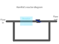
If you were to diagram your current flow, it looks like this:

In this setup, you will get SOME flow control, but because your valve isn't on the "main" flow line (since there really isn't a "main flow line due to the hard 90-degree Tee part), you won't get full control of your reactor's flow.
All you have to do to fix it is:

Here's how it might look for your setup:

By removing the double-90-degree Tee, you allow for a true "path of least resistance" through the arm of the reactor that has the valve on it.
Once the flow turns the initial "corner" into the system, it will want to skip the bypass line and go straight to the valve. This is what you want! Because then you can control the entire flow volume completely with the valve.
Curious, are your inlet/outlet of the yugang reactor centered on the end of the reactor, or offset and can you adjust where they are top/bottom?
If I recall correctly, inlet/outlet positioned higher on the end of the reactor will allow for longer dissolution time, less bubbles, whereas if inlet/outlet are towards the bottom of the reactor, you are getting less dissolution time and more bubbles.... although I may have those backward lol
But something to consider... placement of the inlet/outlet top or bottom of the end of the reactor.
Checkout the 1:30 minute mark.
Last edited:
Curious, are your inlet/outlet of the yugang reactor centered on the end of the reactor, or offset and can you adjust where they are top/bottom?
Either way can work. THere seem to be a mixture of layouts that people use effectively. Some folks have centred inlets and outlets on their Yugangs. The negative of this is that adjustment of CO2 dissolving rates is zero if your keep the reactor horizontal. There is a small amount of adjustment available by tilting the reactor but you basically have to build the reactor to the right size for the individual tank this way.
However, with an offset outlet in particular, this give you a lot of potential adjustment by rotating the reactor whilst keeping it horizontal, to adjust the height of CO2 bubble and thus the surface area available for diffusion. Thus so long as the reactor is large enough it could always potentially be rotated to reduced the CO2 bubble size to fit the tank's needs. once installed this can be difficult as many folks seem to PVC weld their reactors into hard piping. Thus once done its very tricky to adjust. However, in a circuit where the reactor is attached by soft piping and hose clips onto barbed fittings its easy to rotate the reactor a little and re-tighten the hose clips.
Similar threads
- Replies
- 6
- Views
- 392

- Replies
- 17
- Views
- 807
- Replies
- 8
- Views
- 495